![]() TRANSAT CORP.
TRANSAT CORP.
| Application Note: INTERMITTENT ETCH RATE MONITORING |
"AUTOMATIC ETCH CONTROL USING THE CEM-1000"
Intermittent rate monitoring is suitable for etch processes with slowly varying etch rate. The probe is immersed intermittently for the rate measurement and is stored between measurements, preferably in water. This allows prolonged use of the monitor blank.
To assess whether intermittent monitoring is suitable, it helps to first run a continuous etch rate response. From that, one can determine the feasibility of intermittent monitoring. The approach is explained by means of an
EXPERIMENT
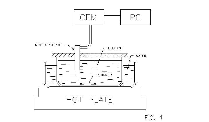
A continuous etch rate response is measured in the setup of Figure 1, which includes 20 MHz monitor blank in a probe immersed in an etch tank that holds ammonium bifluoride at about 70° C, and a stirrer. The tank resides in another container holding water and sitting on a hot plate with On/Off heat regulation and a stirrer drive. The F44 multiplier in the CEM was set to 50.
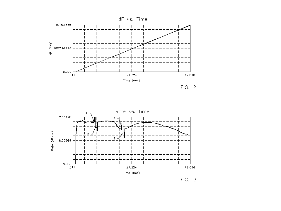
Figures 2 and 3 show the measured frequency response and etch rates for the (imaginary) etch load, i.e. the values shown are twice the values of the measured (single-side) etch response of the monitor.
The curves were obtained as follows:
The probe was immersed in the etchant at approximate time t = 0 (see Fig. 3). After about 8 minutes, the probe was removed at time t = A, briefly immersed in water (of the water jacket of Fig. 1), then re-immersed in the etchant at time t = B. After an acquisition time interval, the rate measurement resumed at point t = C. After about 19 minutes, the immersion-removal-immersion process was repeated. After about 28 minutes, the hot plate was turned off.
Note: In intermittent monitoring, during the intervals between measurements, the probe would normally be stored outside the etchant, preferably in water at the temperature of the etchant. However, in this experiment the probe was kept in the etchant during these intervals in order to measure the continuous etch rate.
The experiment shows:
A) The etch rate fluctuates in response to the crude On-Off temperature control of the hot plate. Because of the relatively fast changes, this etch process would not be suitable for intermittent monitoring.
B) After brief removal and re-immersion, the measured etch rate is approximately the same as before the immersion, i.e. the measurement is repeatable.
C) After immersion, the etch rate is measured within an acquisition time of less than one minute.
MEASUREMENT TIME
In the CEM, the etch rate is calculated from two monitor frequencies that are DF apart. The first of these frequencies is measured upon immersion of the probe. The second is measured after a "measurement time" Dt during which the frequency has changed by DF. The average etch rate during Dt is then computed according to definition (2) below. After the first rate display, consecutive displays follow every Dt/10 seconds. Since the initial frequency readings may be incorrect (for example due to temperature shock, see NOTE 1 below), the rate displays during the first 10 seconds could be incorrect.
The calculation of Dt is based on the following definitions:
(1) Etch thickness removal: DT = DF/F1 x F2 @ DF/F2 [kHz/MHz2]
(2) Etch Rate: DT/Dt = (DF/F2) / Dt [kHz/MHz2/hour]
(3) Relative Frequency Change: DF/F = F44 x r [ppm],
F44 is the multiplier that can be set on the CEM, and r is the typical repeatability of the frequency measurement. The present setting in the CEM is r = 20 ppm.
The average measurement time [Dt] av. can be determined from the frequency vs. time curve (such as Fig. 2). We define F1 = initial freq. (begin of etching), F2 = final freq., Fo = (F1 + F2) /2 = mean frequency, d F = (F2-F1) = total freq. change, d F / Fo = total relative freq. change, dt = total etch time, and obtain
(DF / F) / [Dt]av. = (d F/Fo) / d t [ppm/min], or with (3)
(4) [Dt]av. = F44 x r x d t / (d F / Fo) [min]
EXAMPLE 1: Determine the measurement time for the "experiment"!
The given parameters are: F44 = 50, r = 20, F1 = 20 MHz, F2 = 23.6 MHz, d t = 42 min, d F = 3600 kHz.
From these parameters one obtains d F/Fo = 0.165 = 165000 PPM and, with (4), [Dt]av. = 0.25 [min]
MEASUREMENT ACCURACY
The rate measurement is affected by the limited repeatability of the frequency measurements.The worst-case error is
" Repeatability Error" = 2 x r / (DF/ F), or with (3)
(5) Worst-case Repeatability Error = 2 / F44
The factor 2 accounts for the fact that DF is obtained through two frequency measurements. According to (5), the repeatability error appears to be independent of the repeatability value r. However, note that F44 is inversely proportional to r via eq. (3). Another error occurs due to rate changes during the time interval between measurements. This is discussed next under:
FEASIBILITY OF INTERMITTENT RATE MONITORING
The feasibility depends on whether the etch process can be monitored economically and with sufficient accuracy. This in turn depends on the length of the time interval "I" between measurements. The interval can be determined from an experimental continuous CEM rate plot. This is explained in:
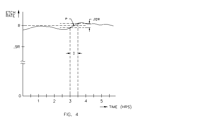
EXAMPLE 2: Fig. 4 shows a hypothetical etch rate plot. Assume you want to determine the between-measurement interval "I" required to measure the rate with an accuracy of 2%. To proceed, assume for now that:
a) the individual rate measurements are perfectly accurate
b) the rate measurement time Dt is small compared to I
c) the rate response is monotonic in the sense that it shows no abrupt changes.
Next, define
(6) "Interval Error" = DR/R,
where R is the average rate during the interval I and DR is the maximum deviation from R during I.
Fig. 4 shows how to find I: Choose the point P with the steepest slope on the rate curve and set its amplitude equal to R. Align two parallel lines marking the 2% error limit central with P. The two lines intersect the rate curve in two points that are separated by the required time interval, which according to Fig. 4 is I = 30 minutes.
The user then needs to decide whether the interval I is large enough to be acceptable for his purposes. Too frequent rate measurements may be too inconvenient and costly.
CHOICE OF THE F44 MULTIPLIER
A explained above, the total measurement error is the sum of the "repeatability" and "interval" errors. Since according to (5) the repeatability error decreases with increasing F44 multiplier, it is desirable to choose a sufficiently large F44 value, provided the measurement time Dt remains small compared to the interval I. If these two conditions are met, the interval error will be larger than the repeatability error.
This is shown in EXAMPLE 3:
For the hypothetical etch process of Fig. 4, the inter-measurement interval I was 30 minutes, based on a maximum interval error of 2%. Assume that the blank frequency changed from 19 to 21 MHz during the marked interval of I. Based on these values, determine the F44 multiplier such that the repeatability error is limited to 1%, then determine the measurement time Dt
From (5) follows: F44 = 2/0.01 = 200 (see NOTE 2 below)
From (3) follows: DF/F = 4000 ppm for r = 20 ppm (typical)
The relative frequency change during I is
dF/Fo = MHz / 20 MHz = 0.1 , or 100000 ppm
From (4) follows: [Dt]av. = 4000 x 30 / 100000 = 1.2 minutes
NOTE 1: The time delay due to thermal shock during the immersion of the probe is described on page 26 of the CEM MANUAL. During this time, the monitor blank is heated to the etchant temperature. If the monitor blank is dry, the heating occurs almost instantaneously (for a 25 MHz blank). If the probe is stored in water before immersion (as was the case for the example in the manual), the delay is increased, unless the water temperature is close to the etchant temperature..
NOTE 2: At present the maximum settable F44 value for the CEM is 1000. If necessary, it could be increased.